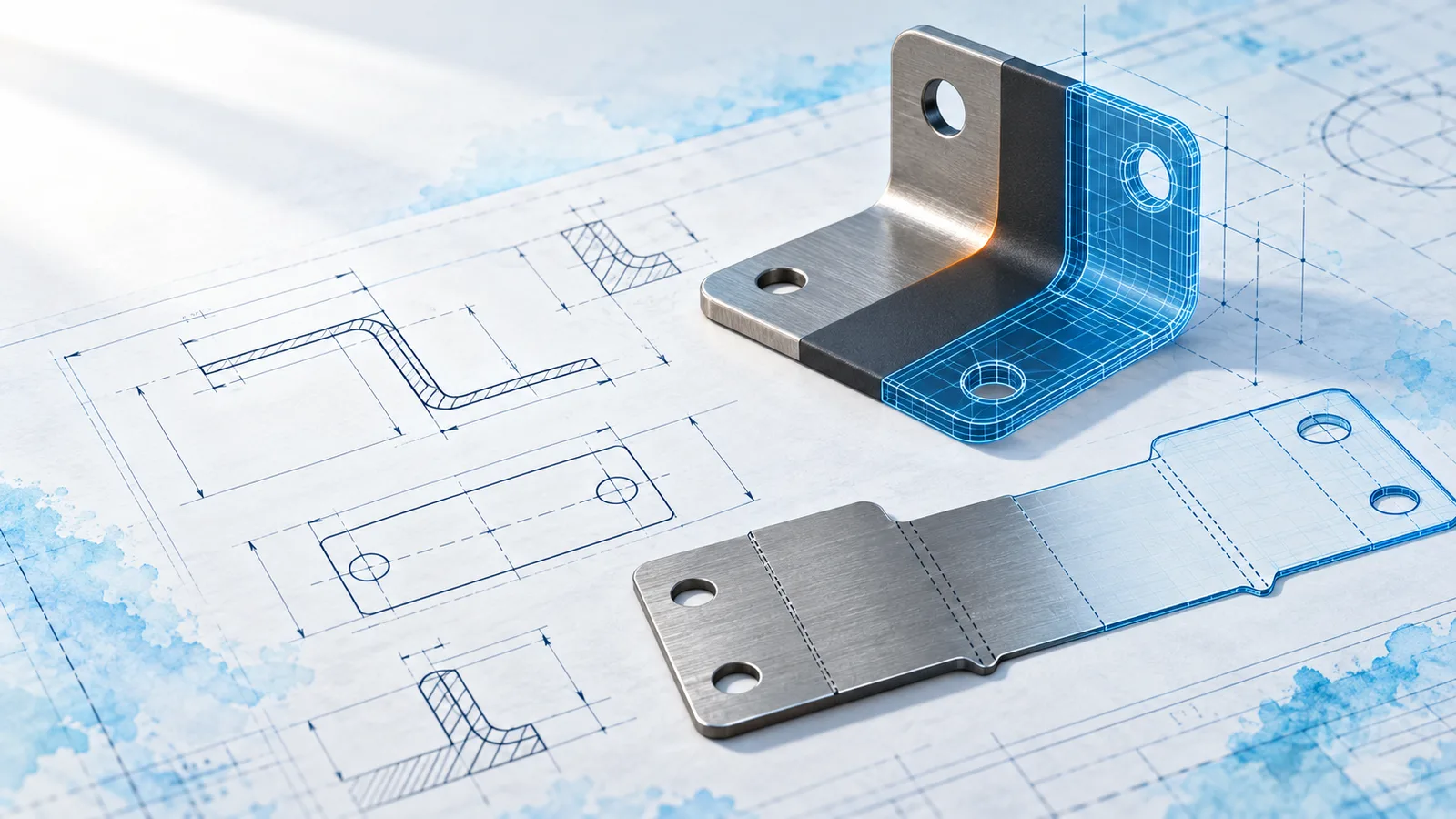
A sheet-metal part is made flat and then bent. Modeling it the same way in SolidWorks gives you a correct flat pattern for the laser cutter and a bend table for the press brake, with no extra drawing work.
Start with the base flange
Sketch the bracket profile and use Base Flange/Tab. Set the thickness and the bend radius here once; every later flange reads them from the Sheet-Metal feature.
Add flanges, then holes
Add the edge flanges, then cut the holes with Extruded Cut and “Link to thickness” checked. Holes cut after the bends stay round in the bent part and are placed correctly in the flat pattern.
Check the flat pattern
Unsuppress Flat-Pattern and export it to DXF. The bend allowance comes from the K-factor, so ask your supplier which value their press brake uses; 0.44 is a common start for mild steel.
Bend allowance = angle × π/180 × (radius + K × thickness)
90° bend, R = 2 mm, t = 2 mm, K = 0.44
= 1.5708 × (2 + 0.88) = 4.52 mm